DF-1 DIY Ferrite Antenna
(Original design by Don Froula IL.)
Yep! It works great!
See the USAtoa Forum pages for Don's original descriptions and methods.
Everything needs a name so I named this with Don's initials since he came up with it!
This describes a duplication based on Don's original design and his findings on the prototype.
The history of this antenna relates to the scarce 2000 Mu ferrite cores needed for this type antenna to work well. By gluing 5 smaller rods in series, Don made it possible to create a core that works just as well as if it was made to that length. That is the tricky part of this whole project. This is the only part you have to take great care with during construction. It's easy if you know what to do!
1. The rods need to be obtained from the link on the forum pages. Make sure you get the right ones! 5 rods are needed for each antenna. The surplus dealer is A1 to do business with!
2. Construct your assembly jig. A 90 degree V will hold the rods while you glue them together. Put wax paper on that with a good corner in the paper to prevent sticking to the jig.
3. Here you have two choices. Both have been made to work. You can use crazy glue or Epoxy. Don had bad luck with the crazy glue and went to Epoxy. After discussing the reason for the crazy glue having problems, shrink was put on first to support the rods before winding. With the crazy glue you can't bend the antenna with any force at all or it will break. You could do a chin up on it if you pull straight down! It has almost no shear strength is the reason why. Carefully place the glued stick into the smallest shrink tubing you can fit over it. Then carefully heat each end first, so that it encloses the ends of the rod. That allows the shrink to pull the rod toward the middle as the rest is heated to shrink it. Be very careful not to heat beyond the point that it shrinks to size, preventing damage to the glue. Epoxy is some bit stronger in this respect but makes a thicker wall between rods, but either will do. You will need different sizes of shrink tubing for different layers.
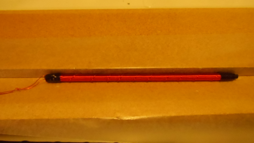
4. Once the shrink is in place use 23-28 AWG enamel wire to wrap the antenna the full length except for 1/4 inch or so on the ends. The exact number of loops is not critical! Just try to make it even with side by side windings. I just happened to have 23 AWG wire and that has been proven to work well.
5. Once you have the windings in place you can put a shield over them. Double some aluminum foil the length of the windings. Make a piece that will go the length and wrap around the core leaving 1/8th inch gap the full length. Prepare a bare wire the length of the antenna plus lead length. That becomes the shield's connecting wire. Place a new length of shrink over the winding layer and shrink in place. Careful of the heat! Now place the foil shield into place down the length of the antenna making sure it does not short across the gap anywhere. Put the bare wire down the length of the foil on the non gap side of the foil. Now we will put a shrink tubing cover over that and shrink into place. If necessary you can use some electrical tape to keep the shield in place while you do this.
6. The finished antenna should look like this. The silver ring on the end is the shield.
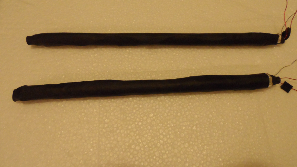
BE VERY CAREFUL NOT TO PUT SIDEWAYS PRESSURE ON THIS ANTENNA UNTIL YOU GET IT IN A SUPPORTING TUBE. But with the layers of shrink and the windings it is actually not too tender anymore and will still work even if a rod should come unglued but not damaged any other way.
Ready for shrink/shield/ and shrink again
Note: Use electrical tape to hold the wires
until you get shrink tubing on it.
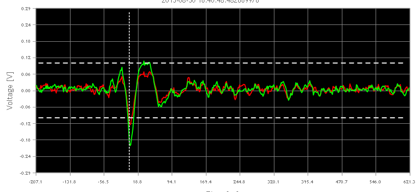
Results after construction
| DF-1 single layer Ferrite DIY Antenna specifications. Tested at 1,10,100 kHz |
1 kHz L=6.773 mH C=3.740 uf. R=3.183 Ohms Z=42.65 Ohms Q=13.3 |
10kHz L=6.124 mH C= 41.44 NF R=18.81 Ohms Z=383.6 Ohms Q=20.1
|
100 kHz L=6.124 mH C= 417.8 PF R=180.0 Ohms Z=3.52 K Ohms Q=20.6 |
When connected to a Red TOA system this antenna had very good performance. Compared to the Flat Panel V.2 the gain is lower but performed very well with higher amp. gain.
If space and location are driving needs, this antenna should serve you well on the TOA net.
A double layer version of this antenna has been constructed for testing but has not yet been fully tested. From what I see, it won't be necessary.
Please refer to Don Froula's original construction plans /tips/ info before starting construction. Mileage may vary.
Note: The key to this project is finding 2000 mu or more ferrite core material. It's rare and expensive in long lengths! These rods are government surplus that may not last long! Other ferrite materials should be highly suspect as to their performance for our use on TOA. Here is all that is known about this source taken from the recommended supplier.
| ICH) ROD7.5/50 Phillips ferrite rod. Soft 3C80 ferrite material great for EMI suppression or tuned coils. EMI suppression DC-200 Mc. RF tuned coils DC-30 Mc. Initial Perm: 2000 ±20%. Saturation flux density: 500 mT. Residual flux density: 210 mT. Mfg. P/N: ROD7.5/50-3C80. 3C80 has been replaced by 3C90. 3C80 is equivalent to Cosmos Ferrite CF196 material. |
Our thanks to Don Froula for finding the core material and doing the proto type ground work for us.
Happy constructing! Let us know your results on the USAtoa forum!
Gerry, WB5TXA
San Antonio, Texas