Flat Panel TOA Antenna Version 2
TOA Lightning Radar Antenna / Radom
Note: Some people requested I return this project from my old TOA site. I hope you find it of some use. It does solve the problem of trashy signals! :)
This is an updated version of the original Flat Panel TOA antenna. The need for weather proofing and mounting came to light with the first version after it was in use for a while. This new design addresses that. Also addressed was the need for a little less gain. The lowest setting for the preamp was 11 and many times that was not low enough. The preamps have more gain than you can use with these antennas ver. 1 and 2.
Materials Needed
1. Materials needed.... (Consult the original version for the panel information.
Note: The panels are a different size and shape than the version 1. Other wise the
construction methods and materials are the same.
2. Enough 26 Gauge enamel wire to supply the 35 turns per loop. (You can do the math.)
3. 4 place terminal strip for wiring.
4 Two lengths of 2 conductor shielded cable of the length needed to reach the preamp.
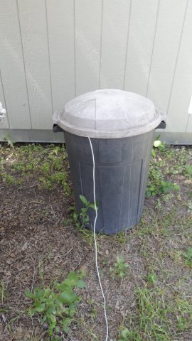
5. The Radom consist of a plastic trash can. These are of different manufacture so just make sure
your Radom size agrees with your antenna size! You can use left over panel board to fashion the
roof over the antenna that supports the preamp. Nothing critical, except make sure you put a strain
relief on the preamp wires and leads. A concrete flat round brick might help to keep from tipping over in the wind.
Secure it in some fashion so you don't end up with a can full of water!
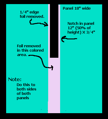
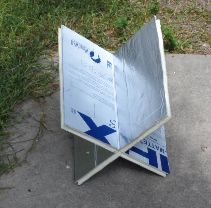
Note: See the graphics below for instructions on making the two panels.
Panel size is 18" wide top, 17" wide bottom, 24" high.
Tapered to fit housing.
Cut panels 3/4" wide in center, 12" slit centered. Make sure
the cuts are not too wide or too deep or the panels will flop! Try to cut
as good as you can to 3/4" so they bind a little when going together.
The two sides then slide together to make the core. Note: The notches in the board center
should be 3/4" wide / 12 inches deep. The boards go into each other 50% of the height. (This was not
stated earlier in the instructions even though it was built that way.) (Thanks for tip Don F.!)
Note the 'V' notch around the areas to receive the wire.
Pictures
Ready to have wire loops wound. 35 turns AWG 26 Enamel Wire each loop.
Note: This is not critical on this antenna. 22 / 26 / 28 AWG should work fine.
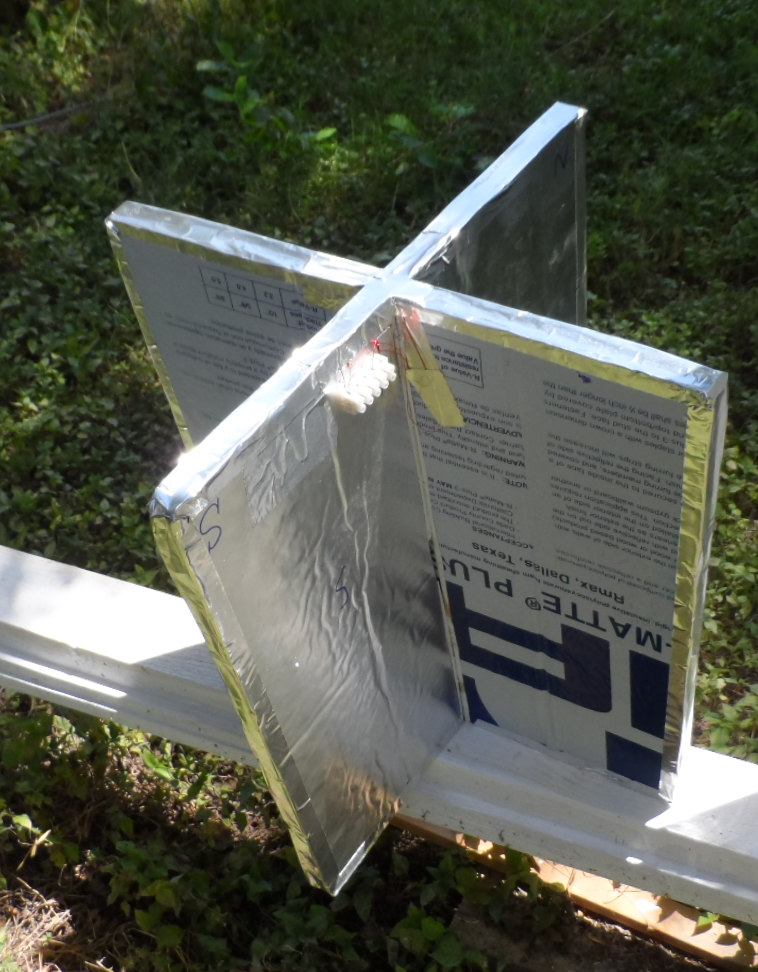
Here is what it looks like after the loops are wired.
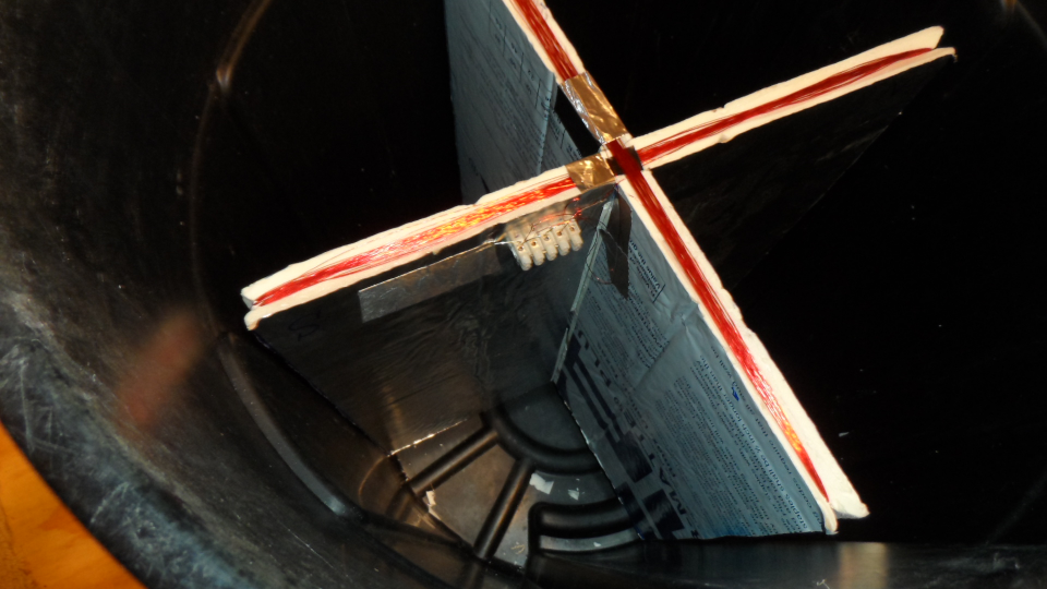
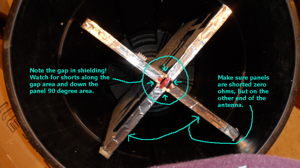
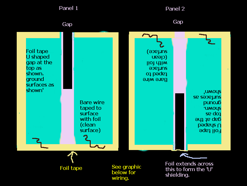
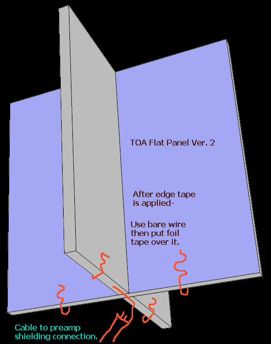
Take special note of the shielding clearances. Each panel is U shaped, with one U crossing the other and shorted on the bottom of the U but open at the top
and down the sides to the bottom of the U. Run a bare wire on the surfaces of the Foil tape on the bottom of the two U panels. Tape the wire to the cleaned surfaces to make
a good connection. This connects the two panels only at the bottom. The shield ground of the signal lines connect to the shield in the same manner. Foil tape over a bare wire laying on the surface. Make sure the printed side has the ink scraped off with a razor blade to make good connections.
Shielding schematic
Here the completed core is ready to go.
Make sure it ohms out. All foil surfaces
should show grounded together. Loops with 26 awg.
35 turns should read just over 8 ohms and not shorted
to ground.
Make a buffer panel that will rest on top of the antenna core.
Left over panel material should work fine. Here a scrap of
packing material does the same. It gives the preamp something
to mount to out of the way of the loops.
Secure the pre amp so that the wires are protected. Use
strain relief's in case the cable is pulled accidentally.
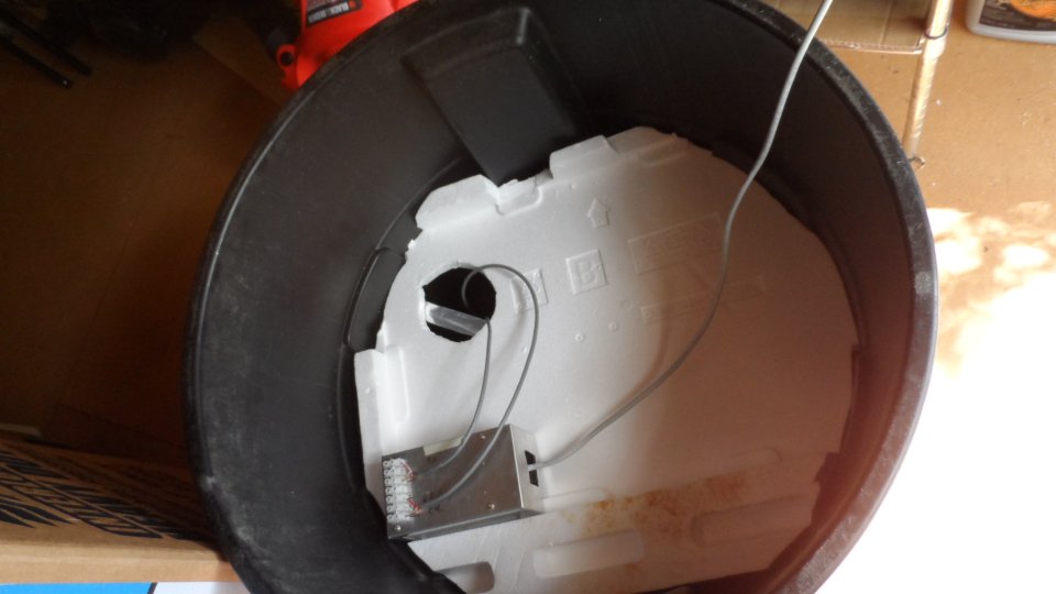
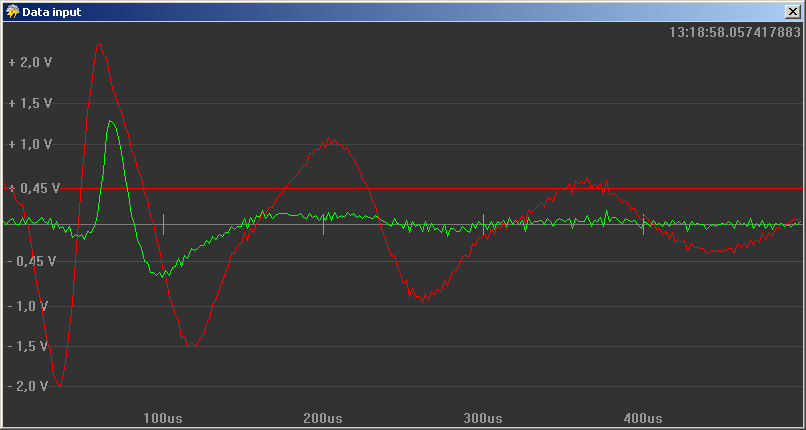
Completed unit online pumping data.
Some first results.
Here is something that happened quite by accident during the time I was off line making connections to the new antenna.
The lightning map had stopped receiving my data during this time and if you look at the Central America area
you can see that the white "most recent" strikes were going away, replaced by red ones.
That made me wonder if I was a major player on those far away strikes as my station is on the far west area. I snapped the current map for later.
Then as the system was running again, I again snapped the plot for comparisons. You can see where the white
strikes started coming back with the new antenna now pumping data in place of the old one. A good accidental
first time test I guess. It does point out how at the present time any one station can make a huge difference in results.
We need to try and stay on the net if at all possible, 24/7/365... Our in commission rate I think is one we all need to talk about more!
Gerry, WB5TXA
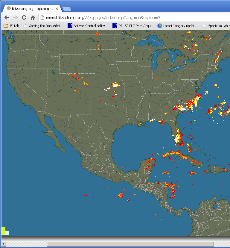
Note the Central America reds during off net connections.
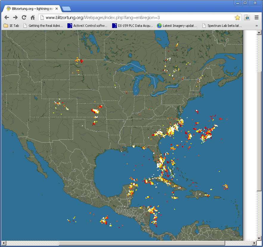
After the Flat Panel Ver. 2 was placed into operation, white recent strikes resumed.
Gerry, WB5TXA
San Antonio, Texas